


In the first part of this article, we mainly talked about the details of the vacuum package of LEDs and some of the precautions in LED SMT process. Here, we will continue the subject and explore more helpful tips for LED SMT operations, so that you can well maintain the performance of LEDs and ensure the overall performance of LED modules and LED screens after SMT operations.
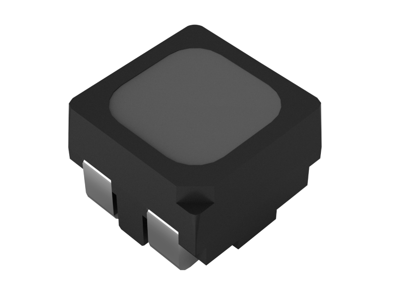
Kinglight 1212 LED
7. During SMT processing, try to use mixed LEDs from different trays or packages to reduce the risk of color deviation and ensure the luminous consistency among different LED panels, and set mixing mode for the SMT machines. But always remember not using LEDs of different production batches at the same time (including left LEDs in previous manufacturing). When making the same LED screen, try to use the same SMT machine and the same reflow oven.
8. If material throwing occurs during the SMT process, priority should be given to checking whether the carrier tape and cover tape are deformed, sized abnormally, drawn, broken, etc., and whether the LEDsare placed sideways or upside down; if there are any abnormalities, feedback should be given in a timely manner; otherwise, it is necessary to check whether the feeder, speed, nozzle height, accuracy, etc. of the SMT machine are normal, and if there are any abnormalities, adjustments should be made in a timely manner.
8-1. Nozzle size: Selecting a suitable nozzle is the key to improving the quality of the LED screen. When performing SMT placement, it’s better to choose a nozzle with a diameter larger than the light-emitting surface of the LED (colloid). This can avoid the nozzle squeezing and damaging the LED when the downward height of the nozzle is incorrectly set, which will result in broken inside wiring and failure of the LEDs.
8-2. Nozzle height setting: When performing SMT on the front side of LEDs, the nozzle height is a direct factor affecting the quality of the LED. If the nozzle moves downward too much, it will compress the LED colloid and cause the internal wiring to deform or break, causing the LED to flicker, not light up, or other quality problems. Generally speaking, it is best to set the nozzle height so that the nozzle moves downward to the position where can just touch the LED pad.
9. If poor tinning occurs during the SMT process, first check whether the LED pins and PCB pads are deformed, oxidized, or whether there are foreign objects between them; secondly, confirm whether there are abnormalities in the solder paste and the furnace temperature. If there are abnormalities, the furnace temperature can be appropriately increased, which can effectively improve the problem of poor tinning.
10. Generally speaking, LEDs can be reflowed twice at most, and the second reflow can only be performed after LEDs being cooled to room temperature after the first reflow. Do not apply any pressure to the LED during reflow. After the LED is soldered, it needs to be cooled to room temperature before other treatments can be performed.
11. The PPAframe of LEDs yellows during the high temperature reflow process. So it’s better to keep the conditions all the same, which means using the same reflow oven for soldering, and the same furnace temperature change curve, and the same chain speed to avoid process differences causing differences in the appearance of the LED panels.
Reflow oven temperature curve recommendations:
11-1. The lead soldering temperature should not exceed 235°C, and the lead-free soldering temperature should not exceed 250°C;
11-2. The temperature in the preheating zone cannot rise too quickly, as too high a temperature will seriously damage the LED; the temperature in the reflow zone should not exceed 250°C and should not exceed 10 seconds.
11-3. If the temperature of the reflow oven fluctuates too much, it is easy to cause color difference in the LED (i.e. inconsistent color rendering), thus affecting the overall display effect of the LED screen. For example, when the maximum temperature difference of different positions of the same module exceeds 5°C during the furnace, it may cause the module to be partially dark, so it is necessary to ensure that the edge of the fixture is hollowed out and ventilated up and down; when the maximum temperature difference of the reflow oven exceeds 5°C in different time periods, and the difference in reflow time exceeds 7 seconds, it may cause color difference between modules.
11-4. When setting the temperature, time, maximum slope, etc. of each temperature zone of the reflow oven, you need to refer to the data provided by the solder paste supplier or manufacturer.
11-5. Recommended temperature soldering curve
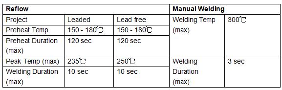
Specific conditions:
Note: if not necessary, it’s better to use leaded soldering.
12. When performing manual soldering, it is recommended to use special tweezers to clamp both sides of the LED and handle it with care to avoid damaging the LED.
12-1. Never hold LEDs by hand: Holding LEDs by hand will cause contamination to their surface, which will affect the optical properties of the LED; in addition, excessive force may cause the LED to deform or the internal wiring to break.
12-2. When using tweezers, do not use excessive force; excessive pressure on the surface of the LED may cause the resin to scratch or peel off, or cause the internal deformation of the LED, break the metal wiring, and affect the performance of the LED or lead to LED failure.
12-3. Be careful to prevent deformation of the LED caused by falling.
12-4. When performing manual welding, avoid using a hair dryer to blow directly on the front of the LED screen; direct blowing from the front will cause the brightness of the normal LED around the failed LEDs to decay too much. Blow from the side of the failed LEDs at a suitable angle. Do not use excessive force when removing the failed LEDs to avoid damaging the surrounding LEDs.
13. After welding, it is recommended to use alcohol (absolute ethanol) for cleaning; when the temperature is not higher than 30°C, cleaning can last for 3 minutes; when the temperature is not higher than 50°C, cleaning can last for 30 seconds; if other similar organic solvents are used for cleaning, it is necessary to confirm whether the solvent will cause corrosion and damage to the LED packaging and epoxy resin.
14. Module glue protection: When building an outdoor LED display panel or LED screen, the module should be protected by glue filling to ensure the moisture-proof performance of the product; glue filling generally needs to be completed within 48 hours after SMT to prevent the module from absorbing too much moisture and being unable to discharge it after glue filling; the glue must be filled enough high to cover the pins of the LED. The specific glue filling height can be determined by referring to the product specification of the corresponding LED.
Continue to read:
Guidance for LED Application & Protection (III) >>>