


By mounting LEDs in an array on the surface of the PCB to form a complete light-emitting surface, we obtain an LED display. In the era of large-pitch LED screens, due to the long viewing distance and the obstruction of the hood, it is difficult for us to find the visual difference caused by insufficient mounting accuracy. In recent years, as the pixel pitch of LED screens continues to decrease, the viewing distance is also getting closer and closer, which puts extremely high precision requirements on LEDs, printed circuit boards, and SMT process. The tilt of the light-emitting surface caused by subtle production and manufacturing process defects becomes obvious when viewed at a close distance, and the issue of sides’ brightness deviation on LED displays becomes prominent. Today, we will explore the cause of the LED display brightness sides’ deviation in detail, as well as the corresponding solutions for the issue.
LED display brightness sides’ deviation means that when you watch an LED display from the left, you get an obviously lower or higher brightness than from the right. This makes the LED display looking either darker or brighter on one side.
As mentioned in the beginning, LED display brightness sides’ deviation is usually caused by its uneven light-emitting surface. And LEDs, PCBs, and SMT process are the main factors affecting the evenness of the light emitting surface of an LED display.
Now let’s proceed to causes of and solutions for LED display brightness sides’ deviation.
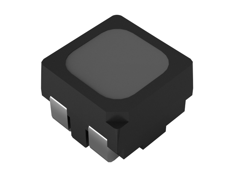
LED display brightness sides’ deviation usually occurs on small-pitch LED screens. So here we’ll focus on the CHIP LEDs and TOP LEDs (both are commonly used for making small pitch LED screens), and see how LEDs can result in the issue and learn how to avoid it.
Unevenly distributed solder paste can result in uneven LED surfaces.
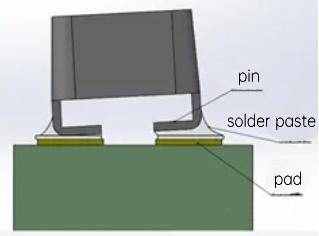
The CHIP LEDs are mounted onto BT substrate, which means the die attach and wire bonding process are performed on the BT substrate; while the TOP LEDs are connected to the printed circuit board by bending the copper pins. Both of the above two types of LEDs may result in sides’ brightness deviation on an LED display. For example, when the bending angle of the pin of the TOP LEDs approaches 90°, the pin and the printed circuit board can achieve a naturally even fit, but when the solder paste on the printed circuit board is not evenly distributed, it will cause the LEDs to tilt. Therefore, in general, when selecting TOP LEDs, we generally do not use LEDs with pins bending in 90 degrees, but use LEDs with hook-shaped pins. The advantage of using LEDs with hook-shaped pins is that there is no need to accurately control the amount of solder paste. When the solder paste is reflowed, the excess solder paste can spread to the redundant space on both sides, thereby ensuring that the LEDs can be evenly attached to the printed circuit board.
Kinglight strictly controls pin flatness and size differences of LEDs to prevent brightness deviation of LED display.
During the SMT process of making LED display panels, precise control of steel mesh printing and furnace temperature is one of the key factors to prevent the issue of brightness sides’ deviation. Generally speaking, the pins of the LEDs for building small-pitch LED screens measure between 0.2*0.2mm and 0.5*0.5mm, so a relatively small steel mesh opening size is required. Small steel mesh openings are likely to cause solder paste to clog the mesh. The corresponding solution is generally to add new coating materials to reduce solder paste drawing; at the same time, clean the steel mesh regularly. In addition, the control of the furnace temperature curve will also affect the melting effect of the solder paste. Actual measurement and monitoring of the furnace temperature curve for each production shift can well ensure the stability of the product.
It should be noted that each LED has a specific direction. Before LEDs enter the furnace, it is necessary to ensure they are in the same direction.
The manufacturing accuracy of the pads on the printed circuit board can also affect the accuracy of the SMT process, which is another key factor in preventing the issue of sides’ brightness deviation on an LED display.
When designing PCB, if the pad size is smaller than the window size, the pad is very likely to deviate from the center of the window. The window position outside the pad is usually sprayed with ink, and the ink is often higher than the pad, resulting in ink accumulation, and blocking the flow of solder paste during reflow soldering, causing uneven distribution of solder paste on the pad, thus causing the LEDs to tilt.
Generally speaking, we can solve the above problems by designing appropriate size relationship between the pad and the window, and strengthening the control of the printed circuit board production accuracy.
In summary, we can prevent the issue of sides’ brightness deviation of LED screens from three aspects: selecting LEDs with hook-shaped pins, precise control of steel mesh printing and furnace temperature, and designing appropriate size relations between the pad of PCBs and the windows.