Why you should build an LED wall for your room
Things need to prepare for the project
Steps to build an LED wall on your own
5. Connect LED strips to power supply
Streaming to a single LED panel
Streaming to all four LED panels
Kinglight provides various LEDs for LED wall manufacturing
Massive LED walls can be seen everywhere we go, either at a shopping mall, or an airport, or any other type of transportation hubs. They make our world looks more colorful and beautiful, and more importantly, present visual contents in a more vibrant and vivid manner. You can either buy or rent an LED wall if you want to promote your business or an event to a new level. But have you ever imagined to build a massive LED wall on your own? Mostly you haven’t. Thanks to Mr. Chris Parker, the tech genius from Tech Random (a YouTube Channel) made one himself, and now we can learn from him. Let’s proceed to the topic today – building a massive LED wall by yourself on a budget.
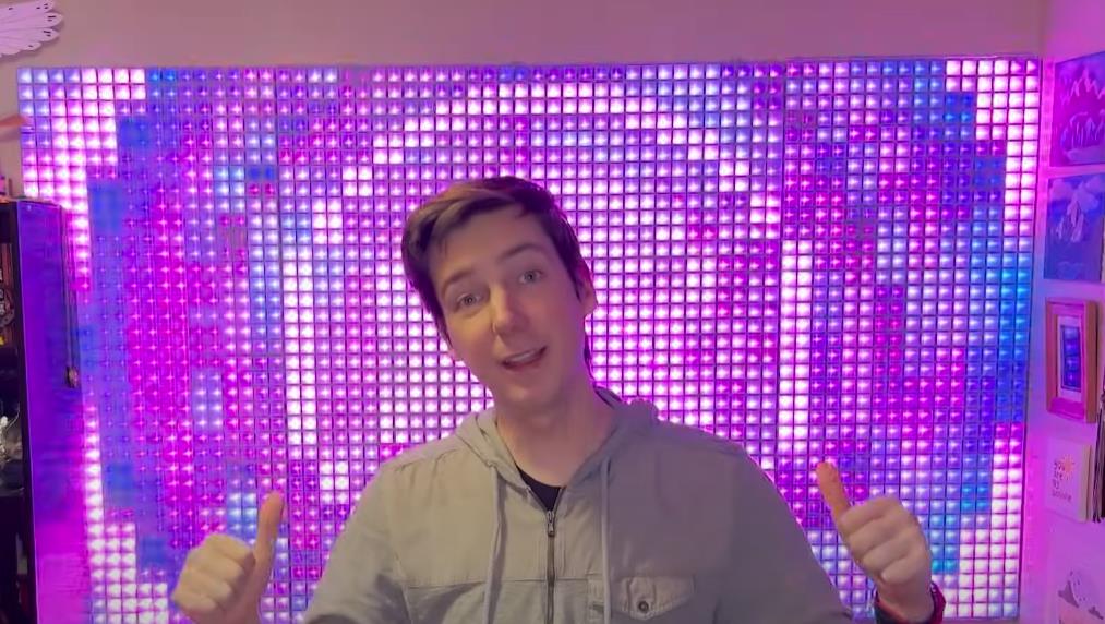
Follow Mr. Kris Parker’s guidance on making a massive LED wall by yourself at a budget
Mr. Christ Parker, the tech genius from the YouTube channel Tech Random built a massive LED wall measuring 7 feet in width with an expense of under 500 dollars. He said, a giant LED wall can add color and movement in your room, and making it feel more lively and fun. And you can use it to stay updated on important information like the time and the weather, or just leave your favourite GIF looping as a unique art piece. For him, he is using mine as a visualizer when he is blasting his favourite music. And it’s also really cool in the background of streams or video calls since it can mirror your PC screen.
Now let’s follow his guidance over how to build an LED wall on your own.
Video origin: Tech Random (YouTube Channel)
First, let’s check what we need for this LED wall building project.
Materials
5m 30P/m (150 Pixels) WS2812b LED strip *16
ESP 8266 microcontroller (6 pack) *1
5V 60A DC power supply *4
AC power cord *4
1kg black PLA filament *1
Light-diffusing cloth *1
36×48 inch cardboard sheets (5 pack) *1
Tools and equipment
3D printer *1
Soldering iron *1
16 gauge wire *1
Wire stripper *1
Duct tape *1
Hot glue *1
Stapler *1
Files needed for the project
https://github.com/TechRandom/Massive-LED-Wall
This tutorial by Mr. Chris Parker will go through every step needs to build the LED panels as well as his kindly suggestions to make the project as beginner friendly as possible. And also you can learn how to use web sockets to communicate with the display over WiFi even if you’ve never used a microcontroller before.
In short, this tutorial will teach everything you need. Let’s get started.
This project needs a lot of 3D printed parts. If you’ve never used a 3D printer before, then now it’s the best time to get into the hobby.
So let’s first download the files for the 3D printed parts on Github: https://github.com/TechRandom/Massive-LED-Wall.
And then, let’s print below parts needed for the project:
8 x ‘Wall Grid 6×6.stl’
4 x ‘Wall crid 4×6.stl’
4 x ‘END Wall Grid 6×6.stl’
2 x ‘END Wall Grid 4×6.stl’
The above 3D printed parts can complete a whole unit for installing an LED panel for the project. So remember to multiply by 4 to cover for the entire LED wall. If you’re going to build a larger one than Mr. Chris Parker, don’t forget to do the math and find out the right volume for your own project.
Let’s first cut the 36*48in cardboard sheets into 21*48inch.
Take 4 strips of LEDs and cut them into 4 segments of 36 LEDs each, and you get 16 strips of 36 LEDs each.
Stick the two leftover strands onto each end of the cardboard to make sure the LED strips are evenly spaced. Stick the LED strips onto the cardboard with a connector end as the beginning.
Also remember to use a level while doing so. This will help you to get the LED strips stay straight the whole way across the cardboard.
Meanwhile, also pay attention to the arrows on the LED strips and don’t forget to alternate the directions of LED strips when you put them onto the cardboard. This will make them connectable for electricity to go through.
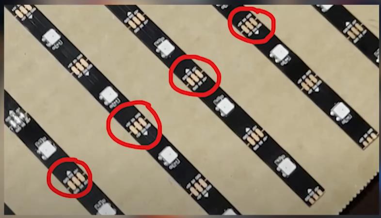
arrow on the LED strip
You can use the wires that come with the LED strips or any other types of wire you like.
Make sure keep a connector
Use a good stripper and soldering station do solder the wires.
Connecting all the LED strips together in a snaking pattern so we get a continuous LED strip.
Use a bit of solder to tin the pad, and then tin the wires and touch them together with iron. Make sure to use pliers since the wires will get very hot during the process.
Before turning off the soldering iron, take the connector we set earlier, and connect it to the ESP8266. Red goes to 5 volts, white to ground, and green goes to D4.
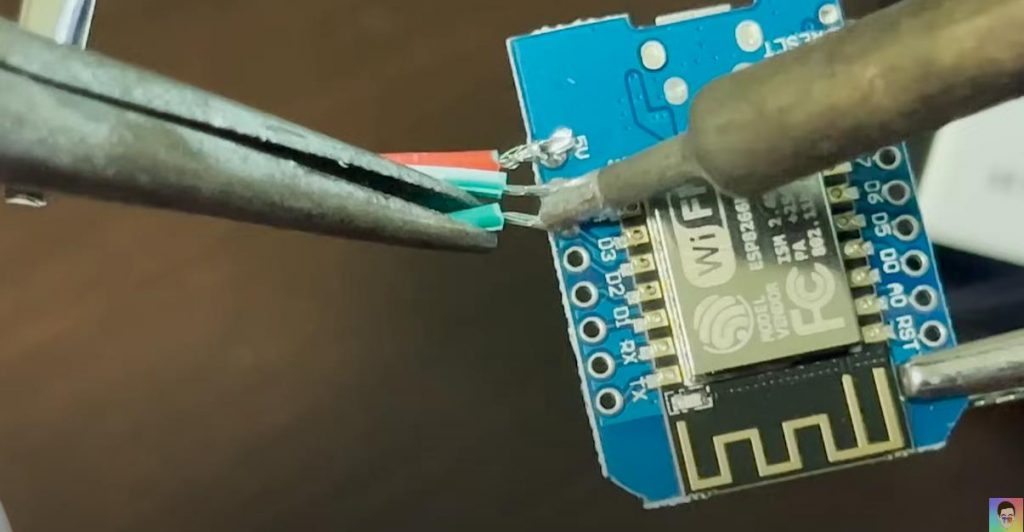
Now we can run the first test to the connected LED strips.
Grab the Arduino IDE from the download section of their website.
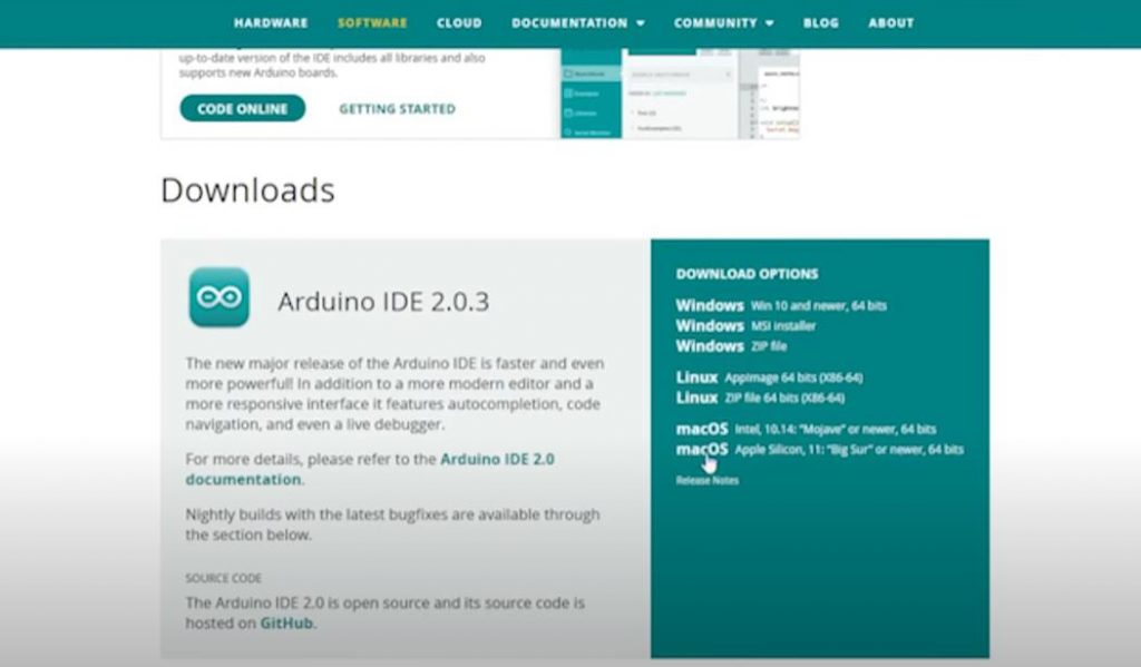
Arduibo IDE download
While it’s installing, head to Github link provided in the beginning, and download the ZIP file. In the folder, open the link.txt and copy its contents.
Now open Arduino and go to file preferences, and paste into additional boards manager. If you already have the stuff here, just separate them with a comma.
Go to “tools – manage libraries”, and install the fast LED library.
When all this gets done, navigate back to the Github folder, and open “FastLED_Test.ino”.
And then click “Tools – Board*** – ESP8266 *** ”, and then select “LOLIN()WEMOS D1 mini (clone)”.
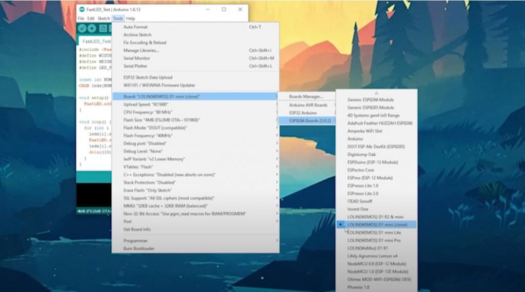
Tools – ESP8266
Then go down to the port and observe a list of options. Plug in your ESP8266 using a micro USB cable.
Close and reopen “Tools – Port “ and you’ll see a new option. Select it and press upload.
With the ESP8266 still connected to your computer, plug it into the LED panel. Then you’ll see a red LED running up and down the LED strip.
Now we have test completes, and the individual LEDs work well.
Let’s connect power supply to the LED strips so we can drive all of the pixels at once.
Cut three equal lengths of 16 gauge wire about 4 feet long. Strip one of the ends and tin the tips, and then solder the red wire to 5 volts and black wire to ground. Space these out as evenly as possible so you can get an even amount of power to each row of pixels.
Then use small strips of duct tape to secure these wires down to the bottom of the cardboard. And wrap the cables together where they meet in the middle.
Now cut the other ends to the same length, and strip them on the longest setting your stripper has. Twist each freight end and bend them at a 90 degree angle.
Before we can connect the power supply, we’ll also have to take a standard AC power cable and cut the end off exposing the three wires inside. You should see a white, black, and green cable if you’re in the US. Strip, twist, and bend these cables as well. Then use a screwdriver to connect the green to the ground, black to neutral, and white to live.
Finally, attach the three red wires to Plus V, and three black wires to Minus V on the power supply.
Now we can run our test with the ESP board disconnected from the LED panel.
Plug into your computer and open the Sketch “MAX_CURRENT_TEST.ino”. Click “Upload” and once the upload is finished, unplug the ESP from your computer, and then plug it back into the LED panel.
Now plug the LED panel into power supply and verify that all LEDs are bright white.
If you spot some pixels turn pink, deliver more power to that section of the LED panel.
Lay out all the 3D printed tiles to make sure you have the right number of each parts.
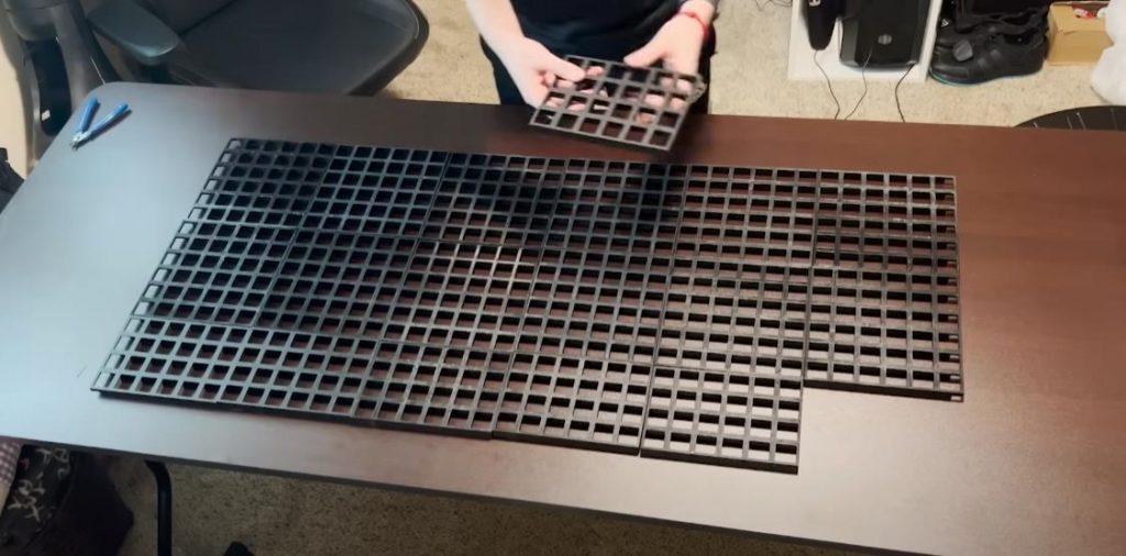
lay out all 3D printed tiles
The end pieces should provide clearance for the solder joints on each strip. Using a high heat hot glue gun to apply 4 drops of hot glue to the bottom of the 3D printed tiles. Then press it firmly onto the LED panel for about 10 seconds.
It’s better to start at the bottom and then work the way up on one side to make sure each tile is squarely fitted.
With all tiles attached, use a box knife to trim down any excess cardboard and make the sides flush with the 3D printed parts.
To add the diffuser, flip the LED panel onto a trimmed sheet of light box cloth. Using a stapler secure the cloth to the back of the cardboard.
Alternate sides as you move down the LED panel, and make sure pull the cloth as tight as possible.
Once the sides are done, you can do the same thing at the top and the bottom. Remember to cut a slit for the cloth and wrap around the power wires at the bottom.
Now we get the first panel for the LED wall done.
To attach the LED panel to the wall, you can use 4 large Velcro command strips per tile to make sure each one is secure but also removable.
Now we can do the same as the above procedures go to get the rest of the 3 three LED panels done for the 7 feet wide LED wall.
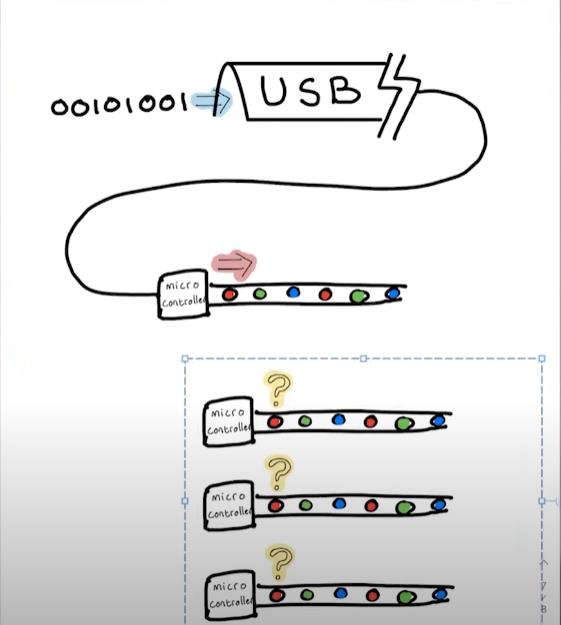
YouTuber Tyler Timoj made an amazing program called LED Matrix Control Software HD or LMCSHD for short. This application allows you mirror your screen play gifs and images, and even use your matrix as an audio visualizer. All the data gets sent to the USB port and can be directly read by ESP boards.
Unfortunately, there is a few issues with the software that needed to be addressed before we can put anything on the screen.
In Tyler’s repository, the vertical pixel orientation is completely broken, and results in these messy images. Thankfully, since the software is open source, Mr. Kris Parker is able to modify the code and fix this issue. And all the files is included in the link provide at the beginning.
LMCSHD Output
The other issue is that this program only outputs to a single serial port. But we have 4 LED panels that all need different data. On top of that, Mr. Kris Parker’s LED wall runs all the way across the room from his PC. So if running a lot of cables, it will make the room an ugly space to stay in.
The solution is to use existing WiFi network and the Web Socket protocol to send the serial data wirelessly to each of the panels.
Web Socket allows for real-time communication between a website and a user’s web browser rather than the client having to continuously request the new data from the server. This allows the server to push data to the clients as soon as it becomes available.
With multiple clients, we can program a server that receives a frame from the serial port, and then splits that frame into four separate frames, and sends each frame to the correct panel. This all happens multiple times per second to give our display a high refresh rate and low latency.
Let’s first experiment with a single LED panel to prove that this will work, and then we can test all four panels together.
Plug the ESP8266 into your computer. Then open the file “Single_LED_Wall_Receiver.ino”. You need set your WiFi SSID and password in here. Then you can upload it to your board. Plug the ESP back into the LED panel, but don’t power it on just yet.
You’re now going to take a fresh ESP8266 and plug it into your computer. Open the file “Singl_LED_Wall_Source.ino”. And once again, set your WiFi SSID and password.
Click upload and wait for it to finish. Then power on the LED panel. You should see a white light indicating power followed by a red or a purple light indicating a connection. Run the LMCSHD.exe, and click serial connect. Select the com port your ESP is on, and set the baud rate to 921600. This is the fasted speed that the ESP8266 can reliably communicate.
The matrix dimensions should auto populate. But if they don’t, enter a height of 36 and a width of 16. Go to “Edit – Pixel Order” and change the orientation to vertical, origin to bottom left, and new line to snake.
Finally, we can click “Start Capture”, and see a squished version of the screen being mirrored onto the LED panel.
Now we can proceed to all four LED panels for a 7 feet LED wall.
Getting all four LED panels to work is just as easy as for a single panel. All you need is 4 ESP boards for panels and an additional ESP board for the server.
Open the file “Multi LED Wall Receiver”, and set your WiFi SSID and password.
Find the function WebSocket event and modify the line: “webSocket.sendTXT(“Device 4”);”.
Connect the first board, and write “Device 1”m, and then upload;
Connect the second board, and write “Device 2”, and then upload again;
Continue until four boards are flashed with their proper device number.
Go ahead and plug each of the boards into their respective panel. One on the left, and four on the right. But wait to power on the display until we’re done with the next step.
Connect the final ESP to your computer, and open the file “Multi LED Wall Source”, and set your WiFi SSID and password, and click “Upload”.
Scroll down until you see the line that says “Set a Static IP address”.
Open a web browser, and enter “192.168.1.121”, and you’ll see this page showing the connection status of each panel.
Power on the display and wait for each panel to connect. If one or more LED panels aren’t connecting, press the reset button on the side of the board, and it will try to re-connect.
Once all the LED panels are connected, run the LMCSHD.exe. And click “Serial Connection”, and select the COM port the ESP is on. Again set the baud rate to 921600.
Also set the color mode to “16 BPP”.
Note: BPP = bits per pixel
Running all four LED panels requires a lot of data over the network. And you’ll notice a low frame rate if you try to run 24 BPP.
The matrix dimensions should auto populate. But if they don’t, enter a height of 36 and width of 64. Go to “Edit – Pixel Order”, and change “Orientation” to “Vertical”, and “Origin” to “Bottom Left”, and “New Line” to “Snake”.
Finally, we click on “Start Capture”, and see an exact copy of our computer screen on the LED wall.
Now that’s it. You’ll be the proud owner of a Jumbotron. You can use the LED wall to watch videos, or play gifs, and press party guests with a music visualizer, or you can challenge yourself to beat some video games at a very low resolution.
Kinglight, as a leading enterprise in LED package across China, provides various LEDs for LED wall manufacturing, including LEDs for rental LED walls, fixed LED screens, either indoor or outdoor LED screens, and small pitch LED displays, etc.
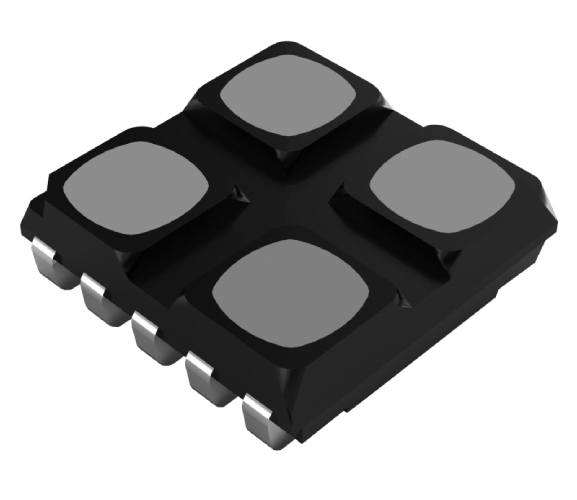
Kinglight 4195 4-in1 LED , featuring high thrust and anti-collision performance, is a perfect choice for rental LED display manufacturing.
For more details, please visit our product page; if you have any questions concerning our product, feel free to write to sales@kinglight.com.